KEMP TECHNICAL JOURNAL · Data Center Series, Part 3
Galvanic current density 49–65% lower, no red rust after 456 hours on assemblies — joint specifications for strut channels, hangers and brackets
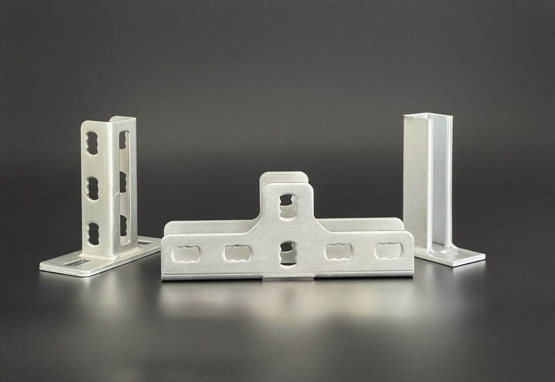
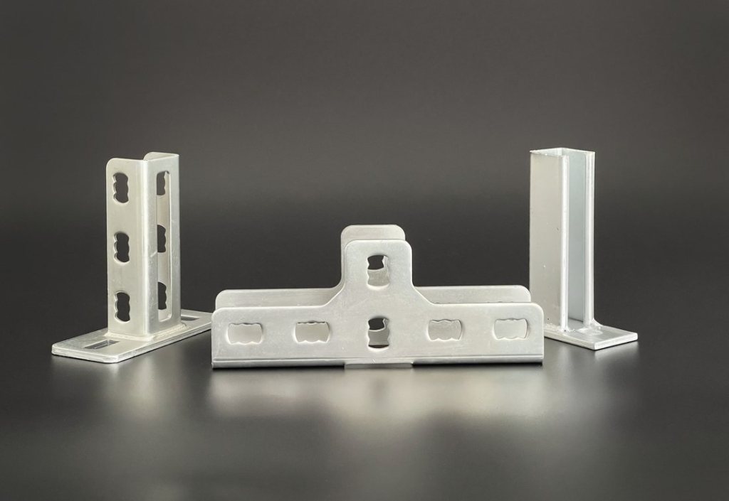
Cable trays, busways, chilled-water and refrigerant pipes, and HVAC ducts run through data center ceilings and beneath raised floors. Threaded rods, strut channels, hangers and brackets hold these services in place, while seismic braces restrain their movement during an earthquake.
These support systems sometimes combine zinc-coated steel members with stainless steel bolts and nuts. Where moisture remains at a joint between the two metals, galvanic corrosion can develop and the zinc layer, which has the lower potential, is consumed first. Once the zinc is depleted, the steel substrate begins to corrode.
A seismic support carries the weight of equipment every day, but it must also perform when an earthquake occurs. Its joints need to retain their clamping condition and cross-section for many years after installation. This article looks in turn at support quantities, seismic requirements, the conditions for galvanic corrosion, and the test values measured by KEMP.
Data center growth in numbers
As data centers grow, so do the services running through their ceilings and floors. Key indicators are shown below.
| Indicator | Value | Basis |
|---|---|---|
| Global data center electricity use | 485 TWh → 950 TWh | 2025 estimate → 2030 projection |
| Growth in global data center demand | 17% | 2025 |
| Data centers in Korea (IT room ≥500 m²) | 165, 60% in the capital region | 2024 |
| Grid capacity of Korean data centers | Approx. 1,913 MW | 2023 estimate |
| KEPCO data center connection applications | 88 (Jan–Aug 2026) / 46 (all of 2025) | Press report |
Sources: IEA, Key Questions on Energy and AI (2026) · Korea Energy Economics Institute, Monthly Energy Statistics (April 2026), citing the Korea Data Center Council · Segye Ilbo (September 28, 2026), citing KEPCO data submitted to the National Assembly
More power means more heat. The IEA estimates that cooling accounts for about 7% of data center electricity use in efficient hyperscale facilities and over 30% in less efficient enterprise facilities. IEA, Energy and AI (2025) Korean data centers use air-cooled systems (60.9%), water-cooled systems (25.4%), outside-air cooling (18.1%) and chilled-water systems (17.4%) (2023, multiple responses, Korea Data Center Council survey).
As busways and cables that carry power, and the chilled-water pipes and ducts that remove heat, become larger and more densely routed, the quantity of supports and the number of bolted joints grow with them.
Support spacing set by seismic standards
Earthquakes are a design condition in Korea. The 2016 Gyeongju earthquake (magnitude 5.8) was the largest recorded since the Korea Meteorological Administration began issuing earthquake reports in 1978, followed by the 2017 Pohang earthquake (magnitude 5.4). KMA, earthquakes ranked by magnitude
The December 2021 amendment of Korea’s Rules on Structural Standards for Buildings raised the importance category of data centers. It applies to buildings whose permit applications were filed on or after December 9, 2021. Korea Ministry of Government Legislation, Rules on Structural Standards for Buildings, Annex 11
| Building | Category | Class | Factor |
|---|---|---|---|
| Public data centers¹ | Special | Special | 1.5 |
| Other data centers | 1 | I | 1.2 |
| General buildings | 2, 3 | II | 1.0 |
¹ Data centers of national and local governments, including those they delegate or entrust.
The importance factor scales the design seismic force. A data center in the “Special” category is designed for a seismic force 1.5 times that of a general building (KDS 41 17 00, Table 2.2-1).
Supports for building services also have numerical requirements. The seismic design standard for building electrical installations (KDS 32 17 10), established in February 2026, sets the following spacing for seismic supports of cable trays, busways and conduits. MOLIT, KDS 32 17 10 revision notice attachment
- Transverse supports — maximum spacing 12 m, within 1.8 m of each end
- Longitudinal supports — maximum spacing 24 m
- Each straight run — at least two transverse and one longitudinal support
- Expansion joints — four-way supports within 1.8 m on each side
For example, a single 100 m straight cable tray run needs at least 10 transverse supports alone (calculated with end supports within 1.8 m and spacing of 12 m or less). Each support includes bolted joints linking the anchor, threaded rod, channel and brace. Neither standard, however, specifies coatings or fastener materials for the supports. The corrosion protection of the joints is left to designers and owners to define for the service environment.
A seismic support is a chain of joints
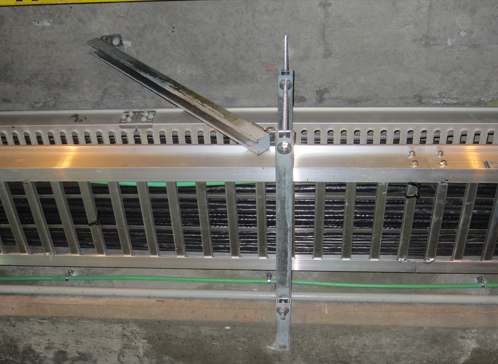
A ceiling-hung support system typically transfers load in the following order.
- Anchor — anchor bolts fixed into the ceiling slab
- Hanger — threaded rods (all-thread rods) suspended down to the level of the services
- Strut channel — C-shaped channel hung horizontally from the hangers, with channel nuts
- Seismic braces and brackets — diagonal members connecting the channel to the slab to restrain horizontal movement
- Clamps and saddles — fittings that secure pipes and trays to the channel
Every connection between members involves a bolted joint. Channels have regularly spaced holes and slots, and site cutting to length creates new cut ends. Bolt holes, cut ends and areas touched by fastening tools are locations where the coating is thinner or more easily damaged.
Reading galvanic corrosion in numbers
Galvanic corrosion requires three conditions: two metals with different potentials, electrical contact between them, and a moisture film connecting their surfaces. Euro Inox, Stainless Steel in Contact with Other Metallic Materials Each condition can be compared numerically.
- Potential difference — galvanized steel –1.05 V and austenitic stainless steel –0.20 V in seawater, a difference of about 0.85 V. A NASA standard classes couples above 0.25 V as not recommended for direct contact.
- Area ratio — an anode (zinc) to cathode (stainless) area ratio of at least 10:1 is recommended. A large zinc-coated member with a small stainless bolt is favorable; the reverse is not.
- Electrolyte — seawater is about 700–1,000 times more conductive than rainwater, so the same contact corrodes at very different rates depending on what wets it.
Sources: NASA-STD-4003 · AGA, Dissimilar Metal Corrosion with Zinc · Euro Inox (calculated from 5×10⁻⁵ for rainwater and 3.5–5×10⁻² (Ω·cm)⁻¹ for seawater)
The 0.85 V difference comes from a strict aerospace standard based on seawater and is not applied directly to indoor building atmospheres. The UK Galvanizers Association rates the additional corrosion of galvanized steel in contact with stainless steel on a scale of 0 (none) to 3 (severe): 0–1 in the atmosphere and 1–2 in seawater. Galvanizers Association, Bimetallic Corrosion (2024) Small stainless steel bolts in large zinc-coated members are usually not a significant problem in ordinary atmospheres, while isolation is considered where conditions are very humid or corrosive, including locations close to salt water. AGA, In Contact with Other Metals Poorly ventilated crevices, such as those under washers or between overlapping plates, retain moisture for long periods.
The consumption rate of zinc itself also varies widely with the environment. Zinc corrosion rates by ISO 9223 atmospheric corrosivity category (first-year exposure) are shown below. AGA, HDG Corrosion Rates for ISO Categories
| Category | Corrosivity | Zinc corrosion rate (μm/year) |
|---|---|---|
| C1 | Very low | Below 0.1 |
| C2 | Low | 0.1–0.7 |
| C3 | Medium | 0.7–2.1 |
| C4 | High | 2.1–4.2 |
| C5 | Very high | 4.2–8.4 |
The upper limit of C5 (8.4 μm) is 84 times the upper limit of C1 (0.1 μm). This is why joint specifications need to vary by location, even within the same data center.
Where moisture persists in a data center
IT rooms are temperature- and humidity-controlled. For IT equipment, ASHRAE recommends 18–27 °C, a dew point of –9 to 15 °C and relative humidity of 70% or lower, and 50% or lower in contaminated environments where silver and copper corrosion coupons exceed 200 Å and 300 Å per month respectively. ASHRAE Thermal Guidelines, 5th ed. (2021) Joints in these spaces carry a low risk of galvanic corrosion. Attention is needed where moisture persists within the same building.
- Around chilled-water pipes and air handlers — when pipe surfaces are below the dew point, condensation forms and wets pipe clamps and channels. In Korea, 17.4% of data centers use chilled-water and 25.4% water-cooled systems.
- Outside-air intake zones — where outside air is used directly for cooling (18.1% in Korea), humidity and pollutants enter with it.
- UPS and battery rooms, and coastal sites — ventilation, chemical exposure and salt add to the conditions.
- The construction period — condensation and leaks can occur before the HVAC system operates, and the supports are already installed by then.
If joint corrosion progresses at these locations, zinc corrosion products and rust accumulate around the fasteners, and the coating around bolt holes and channel nuts is depleted first. Replacing or repairing supports above an operating IT room requires protecting the racks and cables below and securing working space. As explained in Part 1, the paths by which metal particles can fall or enter equipment also need to be controlled around electronics, and zinc whiskers on zinc-based coatings are addressed as observation and evaluation items separate from corrosion resistance.
Comparing surface treatments
The properties compared when selecting surface treatments for supports and fasteners are shown below. Salt spray hours are typical reference values for each treatment.
| Treatment | SST (h) | μm | Process |
|---|---|---|---|
| Electrogalv. | 240 | ≥8 | Ambient |
| Hot-dip galv. | 500 | 50–77 | ~450 °C |
| Innozinc | 720–1,000 | ≥8 | Ambient |
| Innozinc-h | 1,500–2,000 | ≥8 | Ambient |
| Material | Acid (10% HCl, 3 min) | Dissimilar metals |
|---|---|---|
| Electrogalv. | Poor | Poor |
| Hot-dip galv. | Poor | Poor |
| Innozinc | Fair | Good |
| Innozinc-h | Good | Very good |
| SUS304 (base metal) | Good | Fair |
Source: KEMP, data center applications — property comparison by plating method. Salt spray refers to ASTM B117 (5% NaCl, 35 °C); specimens, coating thickness and acceptance criteria are checked together. SUS304 is a base metal rather than a coating, so it is excluded from the white-rust-based hour comparison.
There are several options for specifying joints.
- All stainless steel — no dissimilar-metal contact, but higher material and fabrication costs and harder sourcing of large members.
- Zinc-coated members, stainless fasteners and insulating washers or sleeves — interrupts the current path at the joint, but adds parts and installation checks; one missing part removes the benefit.
- Thick hot-dip galvanizing — a large zinc reserve, but a coating of 50–77 μm adds directly to thread and channel-nut tolerances, and site-cut ends require separate repair.
- Thin ceramic-zinc plating (Innozinc, Innozinc-h) — plating after fabrication covers cut ends and holes, and an 8 μm coating maintains fastening tolerances while lowering galvanic current.
Applying Innozinc-h to carbon steel fasteners as well allows the joint to use a single metal combination, removing the dissimilar-metal contact itself. In this case, the strength grade of the fasteners and the service environment are checked together to evaluate whether they can replace stainless steel fasteners.
Innozinc forms an inorganic ceramic film over the zinc layer
KEMP’s Innozinc is a ceramic-zinc plating technology that combines a zinc layer with an inorganic ceramic film. Zinc provides sacrificial protection for the steel substrate, while the inorganic film restricts moisture and corrosive agents from reaching the zinc surface. The average coating thickness is approximately 8 μm, and the ambient-temperature process reduces the risk of thermal distortion in long channels. The coating structure and fastening tolerances are discussed in detail in Part 1.
Key test values for the high-corrosion-resistance grade, Innozinc-h, are as follows. Innozinc-h test data
| Test | Result | Method |
|---|---|---|
| Salt spray (SST) | 1,500–2,000 h | ASTM B117 / KS D 9502 |
| Cyclic corrosion (CCT) | 80 cycles | JIS H 8502 |
| Adhesion | 5B | ASTM D3359-17 |
| Topcoat adhesion | 3 MPa or more (ISO 20340 pass criterion) | ISO 20340 |
| Pencil hardness | 9H | ASTM D3363-05 |
| Weldability | No defects | Radiographic testing (RT) |
Test values for joint performance
1. Galvanic current density — 65% and 49% lower than hot-dip galvanizing
The rate of galvanic corrosion can be measured as the current flowing between two metals. KEMP coupled hot-dip galvanized and Innozinc specimens to carbon steel and to SS316, immersed them in seawater, and measured galvanic current density with a zero-resistance ammeter (ZRA) for 4–6 hours.
| Paired with | Hot-dip → Innozinc (µA/cm²) | Change |
|---|---|---|
| Carbon steel | 102.38 → 35.52 | −65% (approx. 1/2.9) |
| SS316 | 48.39 → 24.73 | −49% (approx. 1/2.0) |
A lower current density means the zinc coating at the joint is consumed more slowly. The SS316 couple corresponds to a stainless steel bolt joint, while the carbon steel couple corresponds to contact with bare steel at coating damage or with uncoated members.
Seawater is an electrolyte 700–1,000 times more conductive than rainwater, so this test is far more severe than the indoor environment of a data center. The values compare the relative difference between the two surface treatments under the same conditions and do not represent service life. Combinations with SUS304 bolts are evaluated separately on actual assemblies.
2. Seismic support and hanger assemblies — 456 and 1,032 hours of salt spray
KEMP’s in-house laboratory treated seismic supports and hangers produced in Korea with electrogalvanizing and ceramic-zinc plating in the same geometry and compared them (ASTM B117, 5% NaCl, 35 °C). Assemblies are tested with members and fasteners in contact, so the test includes crevices and joints and is closer to the actual service configuration.
Assemblies (456 hours)
| Observation | Electrogalv. | Ceramic-zinc |
|---|---|---|
| First white rust | 48 h | — |
| First slight darkening | — | 288 h |
| First red rust | 192 h | None to 456 h |
| At 456 h | Heavy red rust overall | No red rust |
Individual components (1,032 hours)
| Observation | Electrogalv. | Ceramic-zinc |
|---|---|---|
| First white rust | 96 h | — |
| First slight darkening | — | 268 h |
| First red rust | 264 h | 936 h (rivet nut, slight) |
| At 1,032 h | Heavy red rust overall | Only the rivet nut |
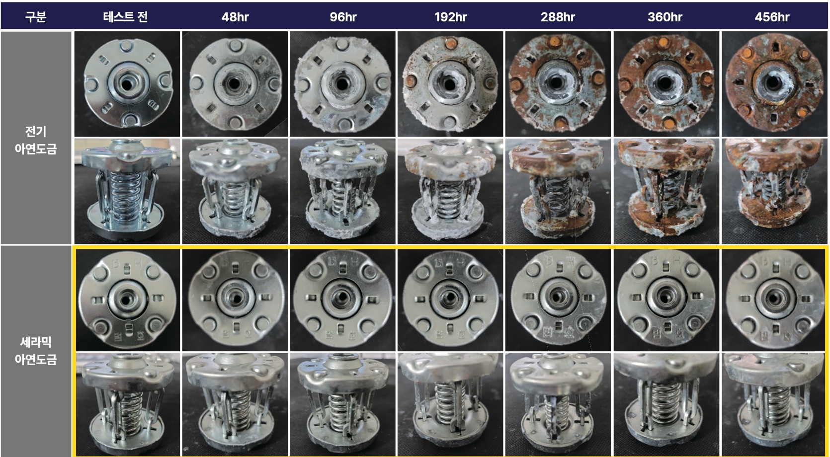
Red rust appeared on the electrogalvanized assembly at 192 hours and spread around the fasteners and springs from 288 hours. The ceramic-zinc-plated assembly kept its surface free of red rust over the same 456 hours. Comparing only the time to first red rust, the assemblies differed by a factor of at least 2.3 (192 hours versus more than 456 hours), and the individual components by 3.5 (264 versus 936 hours).
3. System channel brackets — 480 hours with a thinner coating
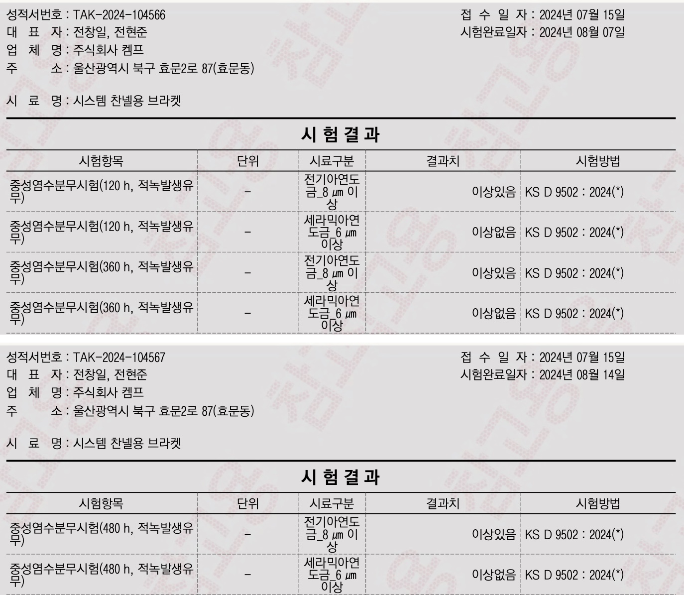
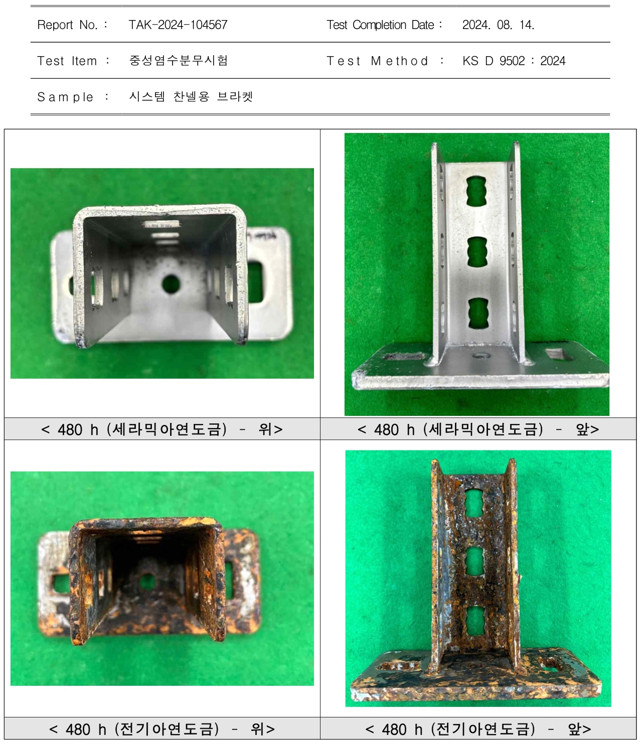
The Korea Testing & Research Institute (KTR) carried out neutral salt spray testing of system channel brackets (KS D 9502:2024, conditions specified by the client).
| Exposure | Electrogalv. (≥8 μm) | Ceramic-zinc (≥6 μm) |
|---|---|---|
| 120 h | Red rust | No red rust |
| 360 h | Red rust | No red rust |
| 480 h | Red rust | No red rust |
Ceramic-zinc plating prevented red rust for at least four times as long (more than 480 hours versus 120 hours) with a coating 25% thinner than electrogalvanizing. At channel nuts and bolt holes, where dimensions must fit, corrosion resistance can be achieved without increasing coating thickness.
4. Comparison with pre-coated sheet (PosMAC) and hot-dip galvanizing
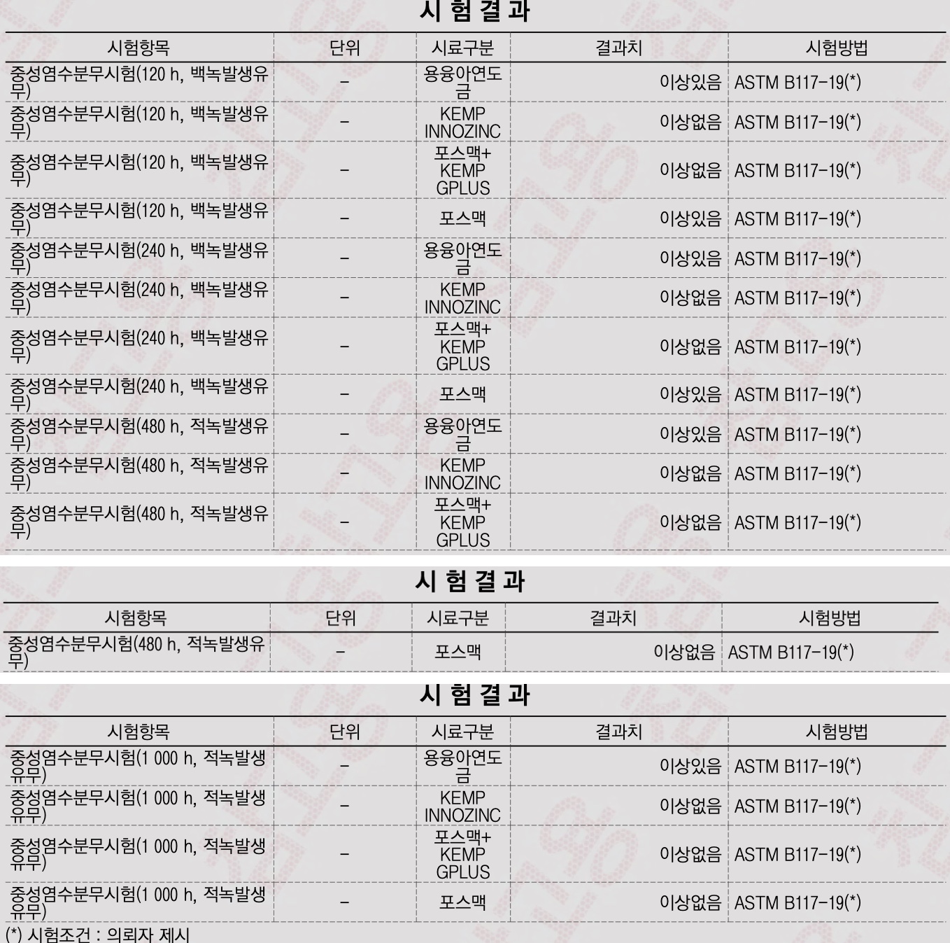
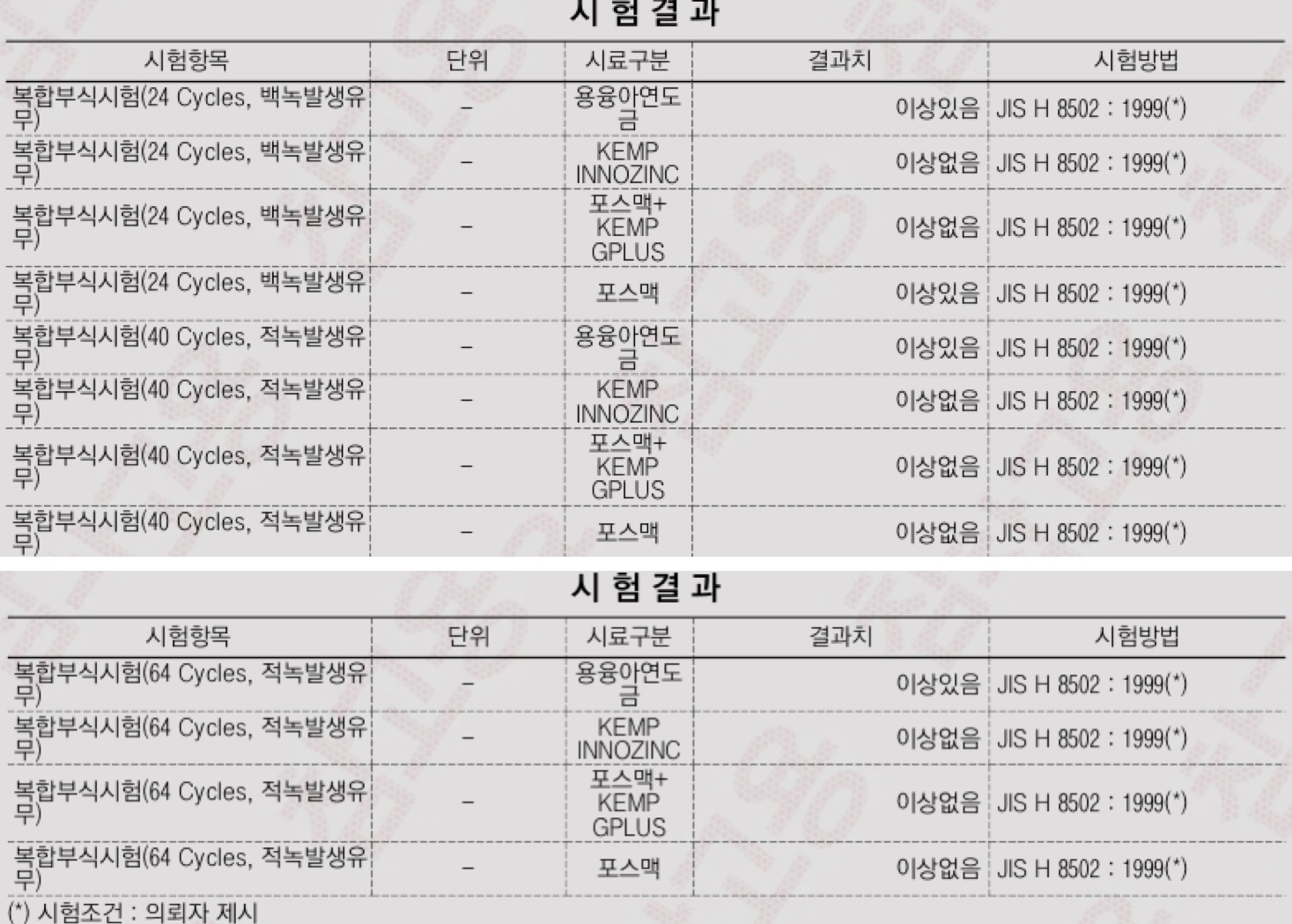
Pre-coated steel sheet is also widely used for strut channels and trays. Results of a KTR comparison on flat panel specimens (conditions specified by the client) are shown below.
| Test point | Hot-dip | PosMAC | Innozinc |
|---|---|---|---|
| SST 120 h, white rust | Yes | Yes | No |
| SST 240 h, white rust | Yes | Yes | No |
| SST 480 h, red rust | Yes | No | No |
| SST 1,000 h, red rust | Yes | No | No |
| CCT 24 cyc., white rust | Yes | Yes | No |
| CCT 40 cyc., red rust | Yes | No | No |
| CCT 64 cyc., red rust | Yes | No | No |
“Yes” means the rust in question was rated as present. Salt spray (SST) ASTM B117-19; cyclic corrosion (CCT) JIS H 8502:1999.
PosMAC prevented red rust up to 1,000 hours and 64 cycles but showed white rust at 120 hours and 24 cycles. Innozinc showed neither white nor red rust under the same conditions. PosMAC with KEMP’s clear inorganic coating G+PLUS added also showed neither white nor red rust over the same periods. These are flat-panel results; components cut and punched from pre-coated sheet must also account for fabricated surfaces where steel is exposed. Innozinc, applied after fabrication, covers these surfaces as well.
5. After fastening-tool damage — 480 hours of salt spray
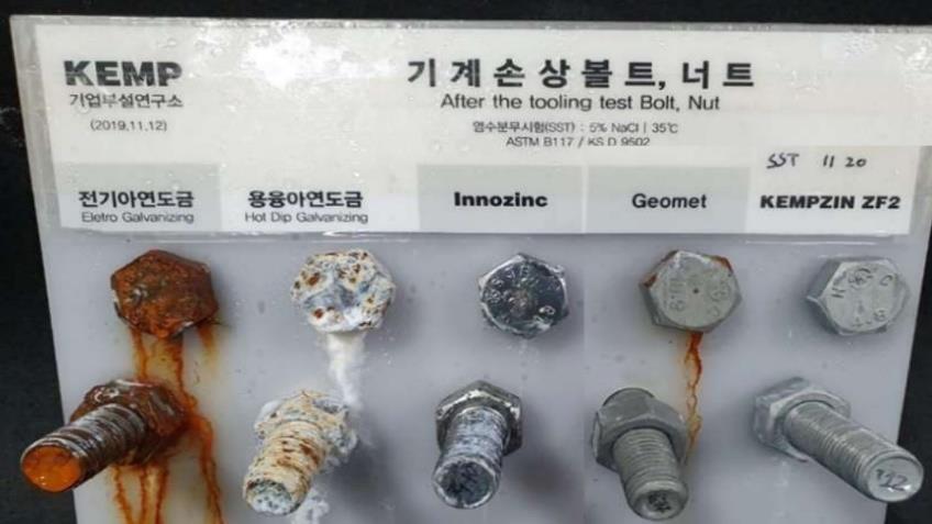
Channel nuts and bolts are damaged by tools during installation. KEMP’s in-house laboratory compared surface treatments after two tooling operations on bolt-and-nut specimens (ASTM B117, 5% NaCl, 35 °C, 480 hours). The hot-dip galvanized specimens showed extensive white corrosion products and some red rust. The Innozinc specimens showed whitening and darkening on the threads, with no red rust.
6. Innozinc-h side by side with SUS304
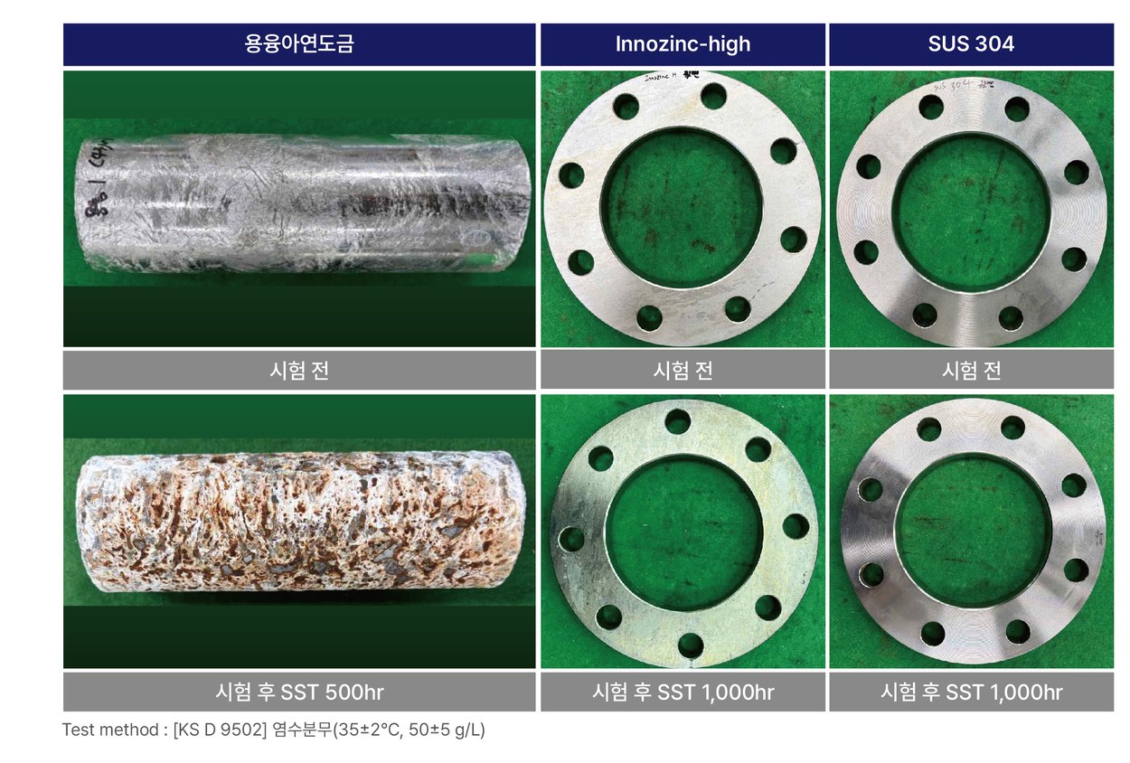
Evaluating whether stainless steel fasteners can be replaced requires a direct comparison with SUS304. In KEMP’s in-house comparison, the surface condition of Innozinc-h and SUS304 was examined after 1,000 hours of neutral salt spray (KS D 9502). The hot-dip galvanized specimen in the comparison is shown at 500 hours.
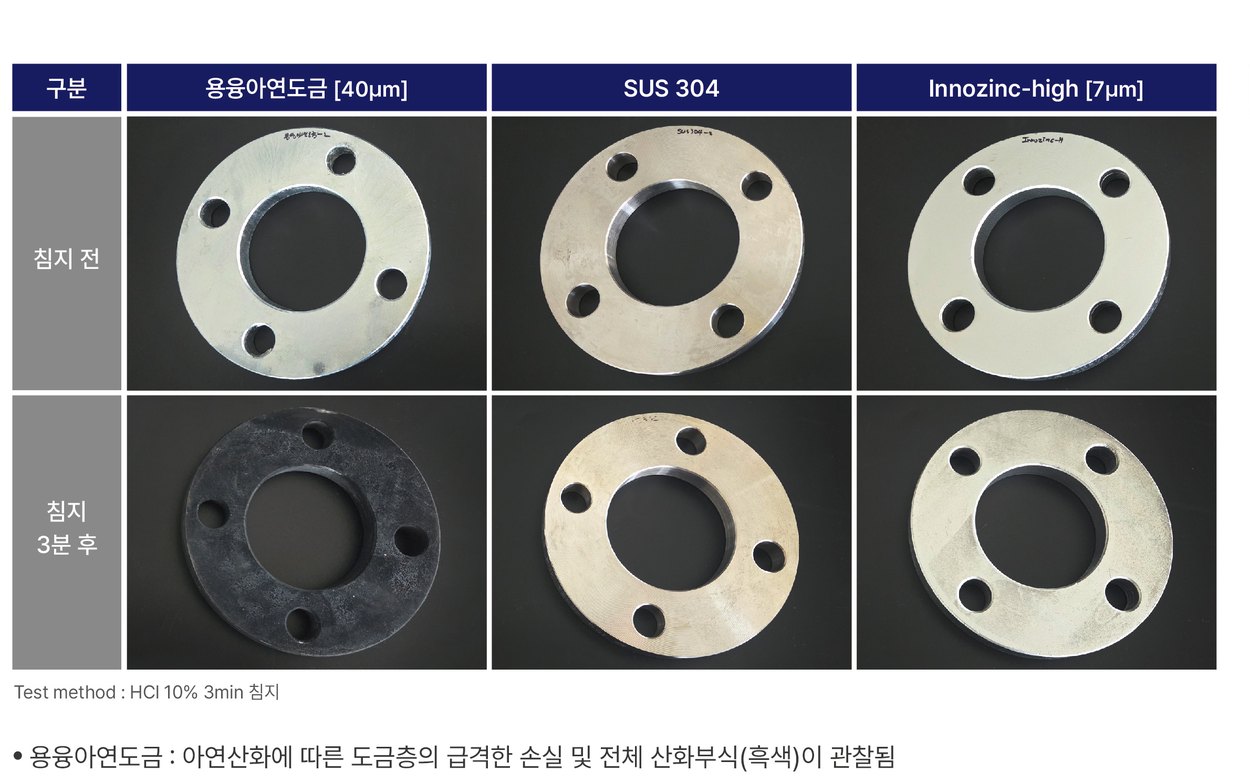
In an acid-resistance comparison involving 3 minutes of immersion in 10% hydrochloric acid, hot-dip galvanizing (40 μm) showed coating loss and darkening, SUS304 showed no discoloration, and Innozinc-h (7 μm) showed only slight discoloration. Innozinc-h achieved this at about one sixth of the hot-dip coating thickness. These results refer to this short-duration immersion; actual chemical environments are evaluated separately according to the substance, concentration and temperature.
7. Electrical conductivity — on par with hot-dip galvanizing despite the film
Where cable trays and supports form part of a grounding or bonding path, it must be confirmed that the surface film does not hinder electrical contact. Korea Polymer Testing & Research Institute measured the electrical properties of plated steel sheet (ASTM D991, 23 ± 2 °C, 45 ± 5% RH; average of five runs on each of two specimens).
- Ceramic-zinc plating, 10 μm — surface resistivity 1.3×10⁻⁴ Ω/sq, volume resistivity 2.1×10⁻⁵ Ω·cm, conductivity 5.0×10⁴ S/cm
- Ceramic-zinc plating, 20 μm — surface resistivity 1.6×10⁻⁴ Ω/sq, volume resistivity 2.6×10⁻⁵ Ω·cm, conductivity 4.2×10⁴ S/cm
- Hot-dip galvanizing, 53 μm — surface resistivity 1.5×10⁻⁴ Ω/sq, volume resistivity 2.5×10⁻⁵ Ω·cm, conductivity 4.3×10⁴ S/cm
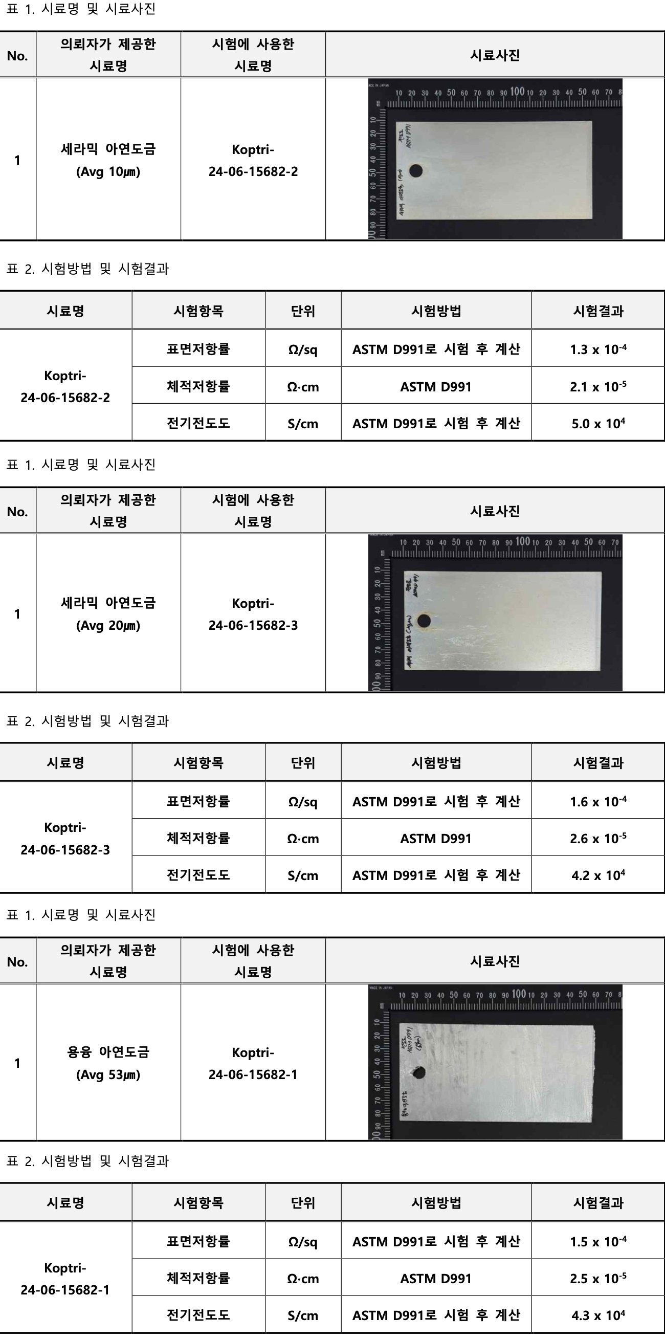
The three specimens fall within the same order of magnitude. Surface conductivity with the inorganic ceramic film remained at the same level as hot-dip galvanizing. Because these are plated-sheet measurements, the resistance of actual grounding connections is checked separately on assemblies.
Plating after fabrication and a thin coating determine production quality
Many seismic support components are cut, punched, bent or welded. When they are made from pre-coated sheet, cut ends and punched holes expose the steel substrate, while hot-dip galvanizing involves immersion in a zinc bath at approximately 450 °C and requires control of thickness variation and thermal distortion. Because Innozinc is applied at ambient temperature to finished components, it can cover cut ends, punched holes and the welds of post bases.
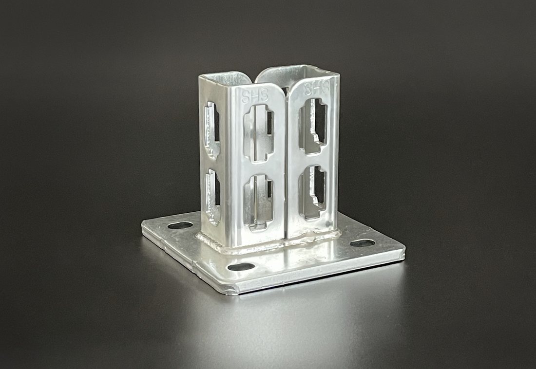
A thin coating is linked to fastening quality. On channel nuts, threaded rods and clamp bolts, coating thickness translates directly into thread tolerance. Compared with 50–77 μm of hot-dip galvanizing, an average coating of 8 μm helps maintain fastening specifications that are verified with thread gauges and trial assembly.
Compare repair conditions as well as material prices
The economics of a joint specification cannot be judged from component prices alone. Converting to stainless steel raises material and fabrication costs, and using insulating parts adds procurement and installation checks. Conversely, neglected joint corrosion can lead to support repairs above an operating IT room, carried out while protecting the racks and cables below. Each of the ten or more supports in a 100 m run can become such a repair.
The process also differs. Because Innozinc is an ambient-temperature process, KEMP’s catalogue states that it can reduce carbon emissions by 65% compared with hot-dip galvanizing (plating process stage). Without a heated zinc bath, the risk of thermal distortion in sheet and long members is also lower.
Thin ceramic-zinc plating improves joint corrosion performance while retaining the fabrication and cost structure of zinc-coated members. Within a single project, specifying Innozinc for general IT room areas and Innozinc-h where condensation, salt or stainless steel contact overlap helps manage both performance and cost.
KEMP began supplying threaded rods and cable trays to data centers in South Korea in June 2026. Plating specifications for strut channels, brackets and hanger fittings can be reviewed within the same production system.
Which grade for which area
| Location | Condition | Grade |
|---|---|---|
| Controlled IT rooms | 18–27 °C, RH ≤70% | Innozinc |
| Chilled-water pipes, air handlers | Condensation | Innozinc-h |
| Outside-air intake zones | Humidity, pollutants | Innozinc-h |
| UPS and battery rooms | Chemical exposure | Innozinc-h |
| Coastal sites | Salt (C4–C5 possible) | Innozinc-h |
| Many stainless bolt contacts | Dissimilar metals | Innozinc-h¹ |
¹ Or apply Innozinc-h to the fasteners as well.
Information needed for an application review
Send the following so that KEMP can propose plating specifications and test items suited to your joint conditions.
- Support drawings and parts list (member materials, fastener material and grade, including whether SUS304 or SUS316 is used)
- Installation location and environment (condensation zones, outside-air intake, battery rooms, distance from the coast)
- Required tests and acceptance criteria (salt spray duration, galvanic evaluation, assembly testing, electrical properties)
- Quantities and delivery schedule
Where specimen evaluation is needed, the test scope is agreed using the actual components and fastener combinations.
Data center applications · Innozinc-h · Samples and testing
Previous articles: Part 1: Data Center Cable Trays and Threaded Rods — Corrosion Resistance and Assembly Quality · Part 2: Data Center HVAC Coil Corrosion Protection with HiGANiC
Sources KEMP technical data (galvanic current density test), KEMP in-house laboratory comparisons (seismic supports and hangers, tool-damaged bolts, Innozinc-h and SUS304), Korea Testing & Research Institute tests (system channel brackets TAK-2024-104566 and 104567; flat-panel comparison TAK-2020-173568, 173570, 173571 and 173572), Korea Polymer Testing & Research Institute tests (electrical properties 24-10769, 10770 and 10771), and KEMP website and catalogue product information. External sources are linked next to the relevant sentences.


답글 남기기